STM32 - Memory

Created:2018-02-08  Last modified:2018-02-08


  1. Introduction

    The STM32 has a uniform address space that ranges from 0x0000_0000 to 0xffff_ffff. The memory section discussed in this note is from 0x0000_0000 to 0x2000_0000. This section consists of the flash memory (0x0800_0000 - 0x0801_ffff, 128KB), system memory (0x1fff_f000 - 0x1fff_f7ff, 2K) and option bytes (0x1fff_f800 - 0x1fff_f80f)

  2. Start Sequence

    STM32 can start execute program from three location. 1). flash; 2). system memory; 3). SRAM

    It can be configure by the boot pins (boot1 and boot0, they are not pins of GPIO)

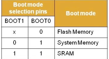
    Start from system memory or flash

    The memory address space (boot space) from 0x0000_0000 to 0x0800_0000 can map to either the flash memory or system memory. It depends on the boot pins. For example, when boot1 = 0 and boot0 = 1, this section maps to system memory.

    The PC (program counter) starts from 0x0000_0004, to load the reset handler address. It is equivalent to load from the 0x1fff_f004.

    A linear memory translation (MMU, hahaha). The program code use the boot space (virtual address), but the hardware use either flash memory or system memory (physical address).

    Start from SRAM

    Because SRAM cannot be mapped to the boot space. Without the translating, the program has to directly use the physical address. Including the vector table, it has to add an offset.

    //SRAM_BASE = 0x2000_0000 physical
    //VECT_TAB_OFFSET = 0x0000_0000
    //FLASH_BASE = 0x0000_0000 virtual
    #ifdef VECT_TAB_SRAM
      SCB->VTOR = SRAM_BASE | VECT_TAB_OFFSET; /* Vector Table Relocation in Internal SRAM. */
    #else
      SCB->VTOR = FLASH_BASE | VECT_TAB_OFFSET; /* Vector Table Relocation in Internal FLASH. */ 
    #endif
    
  3. System Memory

    The 2 KB system memory is read-only, cannot be programmed. It is pre-programmed by ST during production. This section contains code for downloading application code to the flash memory via UART1. It is part of the ICP (ISP) method.

    * Atmega328p does not have this feature.

    Terms

    • ICP (In-circuit programming), programming the flash memory via a hardware, such as JTAG, SWD protocol or the boot loader in the system memory.
    • ISP (In-system programming), same as ICP
    • IAP (In-application programming), developer write a function that can modify the flash memory (code) via any of the microcontroller's interface, such as UART, SPI, and I2C. Arduino bootloader is in this categroy.

    The program in the system memory can interact with the PC side UART via pre-defined command.
    UART command reference

    Example

    1. host send 0x7f: to start communicating.
    2. host sent 0x00 0xff (get): to get the bootloader version and avaliable command.

    * ACK = 0x79, NACK = 0x1f

    Flash loader demonstrator

    ST provides a PC side software called flash loader demonstrator, which is used to upload the .bin file to the flash memory.
    Download

  4. Flash memory

    STM32 F103RB has a 128KB flash memory that is divided into 128 1KB pages.

  5. Option Bytes

    16 bytes

    Configure the protection of the flash memory.